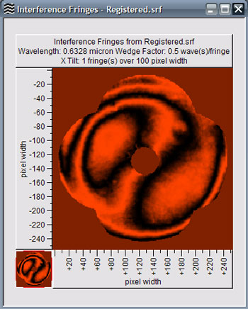
Interference fringes can be simulated from a surface using the Analysis | Interference | Fringes menu item while viewing surface data. Alternately, the ![]() button can be used.
button can be used.
![]()
![]()
Calculation Options 
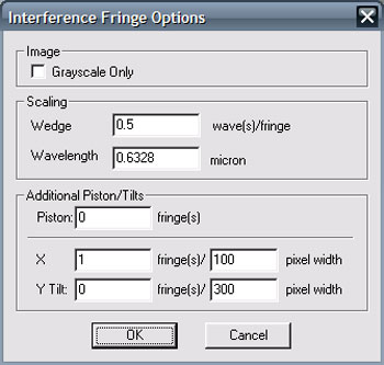
| Grayscale only | Interference fringe images are, by default, color coded based on the simulation wavelength. This behavior can be defeated by selecting this option. The interference image will contain only grayscale values. |
| Max. Image Resolution | The maximum number of horizontal or vertical pixels used in the fringe image. |
| Wedge factor | Scale factor relating wave of surface height to simulated fringe. 1 fringe is always equal to 1 wave of optical path difference (OPD). For a single pass interferometer with a single reflection from the test surface, this value is 0.5 wave of test surface height error per wave of OPD. |
| Wavelength | Wavelength of the simulated coherent light source. |
| Added Piston/Tilts | Piston and tilt terms to add to the simulation. Units are specified in waves of optical path difference. |